
Imbert Gasifier
Here's a basic overview of the Imbert gasifier, taken from the FEMA report. This is covered in more detail in the second section.
The constricted hearth, downdraft gasifier shown in Fig. 1 is often called the 'Imbert' gasifier after its inventor, Jacques Imbert. It has been commercially manufactured under various names. These units were mass produced during World War II by automotive companies including General Motors, Ford, and Mercedes-Benz. A list of known manufacturers is here. These units would have cost about $3000 in 2010 dollars. But when World War II started, it took six to eight months before factory-made gasifiers were widely available. Thousands of Europeans were saved from certain starvation by homemade gasifiers made from washing machine tubs, old water heaters, and oxygen cylinders. Surprisingly, the operation of these units was nearly as efficient as the factory-made units. The homemade units only lasted for 20,000 miles with many repairs, while the factory-made units operated, with few repairs, up to 100,000 miles.
Description
In Fig. 1, the upper cylindrical portion of the gasifier unit is simply a storage bin or hopper for wood chips or other biomass fuel. During operation, this chamber is filled every few hours as needed. The spring-loaded, airtight cover must be opened to refill the fuel hopper; it must remain closed and sealed during gasifier operation. The spring permits the cover to function as a safety valve because it will pop open in case of any excessive internal gas pressure.
About one-third of the way up from the bottom of the gasifier unit, there is a set of radially directed air nozzles; these inject air into the wood as it moves downward to be gasified. In a gas generator for vehicle use, the downstroke of the engine's pistons creates the suction force which moves the air into and through the gasifier unit; during startup of the gasifier, a blower is used to create the airflow. The gas is introduced into the engine and consumed a few seconds after it is made. This gasification method is called "producer gas generation," because no storage system is used; only that amount of gas demanded by the engine is produced. When the, engine is shut off, the production of gas stops.
During normal operation, the incoming air burns and pyrolyzes some of the wood, most of the tars and oils, and some of the charcoal that fills the constricted area below the nozzles. Most of the fuel mass is converted to gas within this combustion zone. The Imbert gasifier is in many ways self-adjusting. If there is insufficient charcoal at the air nozzles, more wood is burned and pyrolyzed to make more charcoal. If too much charcoal forms, then the charcoal level rises above the nozzles, and the incoming air burns the charcoal. The combustion zone is maintained very close to the nozzles.
Below this combustion zone, the resulting hot combustion gases - carbon dioxide (CO2) and water vapor (H2O) - pass into the hot charcoal where they are chemically reduced to combustible fuel gases: carbon monoxide (CO) and hydrogen (H2). The hearth constriction causes all gases to pass through the reaction zone, thus giving maximum mixing and minimum heat loss. The highest temperatures are reached in this area.
Fine char and ash dust can eventually clog the charcoal bed and will reduce the gas flow unless the dust is removed. The charcoal is supported by a movable grate which can be shaken at intervals. Ash buildup below the grate can be removed during cleaning operations. Usually, wood contains less than 1% ash (by weight). However, as the charcoal is consumed, it eventually collapses to form a powdery charcoal/ash mixture which may represent 2 to 10% (by weight) of the total fuel mass.
Cooling and filtration for the lmbert gasifier consisted of a water filled precipitating tank and an automotive radiator type gas cooler. The precipitating tank removes tars and most of the fine ash from the gas flow, while the radiator further cools the gas. A filter containing a fine mesh is used to remove the last traces of any ash or dust that may have passed through the cooling unit. Once out of the filter unit, the wood gas is mixed with air in the vehicle's carburetor and is then introduced directly into the engine's intake manifold. [Some point out that this system of filtration was woefully inadequate; far better systems have since been devised. Read more on cooling and filtration.]
The Imbert gasifier requires wood with a low moisture content (less than 20% by weight) and a uniform blocky fuel in order to allow gravity feed through the constricted hearth. Twigs, sticks, and bark shreds cannot be used. The constriction at the hearth and the protruding air nozzles present obstructions to the passage of the fuel and may create bridging and channeling followed by poor quality gas output, as unpyrolyzed fuel falls into the reaction zone. The vehicle units during World War II had ample vibration to jar the carefully sized wood blocks through the gasifier. In fact, an entire industry emerged for preparing wood for use in vehicles at that time (Reed and Jantzen 1979). The constricted hearth design requires very uniform blocky shapes. This limitation makes the Imbert gasifier less flexible for emergency use.
In summary, the World War II Imbert gasifier design has stood the test of time and has successfully been mass produced. It is relatively inexpensive, uses simple construction materials, is easy to fabricate, and can be operated by motorists with a minimum amount of training.
From the Handbook of Biomass Downdraft Gasifier Engine Systems
5.7 The Imbert Downdraft Gasifier
5.7.1 Introduction
The nozzle (tuyere) and constricted hearth downdraft gasifier shown in Figs. 2, 3, and 4 is sometimes called the "Imbert" gasifier (after its entrepreneurial inventor, Jacques Imbert) although it was produced by dozens of companies under other names during World War II. Approximately one million of these gasifiers were produced during World War II, at a cost of about $1000 U.S, (1983) each. It is important to realize that the cost of producing such a unit today would depend primarily on the degree to which it could be mass produced since none of the components are inherently expensive. Air gasifiers can be operated either by forcing air through the fuel (pressurized) or by drawing the air through the fuel (suction). In practice, gasifiers that fuel engines generally use the suction of the engine to move air through the gasifier and cleanup train. These are called "suction gasifiers". We will describe only suction gasifiers here; however, only minor modifications are required to build pressurized gasifiers. (See Chapter 8, which deals with the topics of blowers, fans, ejectors, and compressors). A large number of descriptive articles on gasifiers appeared during World War II, but no detailed drawings have been located from that period. Fortunately, formulas for determining critical dimensions are given in a number of the older references (Gengas 1950; Schliipfer 1937). Renewed interest in biomass gasification has manifested itself in the fact that a number of individuals and groups have built modern versions of the Imbert gasifier. Plans and manuals for constructing some of these designs are available from several groups (Mother 1982: Skov 1974; Nunnikhoven 1984; Rissler 1984). Some of these gasifiers have been attached to cars and trucks that have succeeded in traversing the country on several occasions. In particular, Mother Earth News and its subsidiary, Experimental Vehicle News, have performed extensive tests on gasifiers and have published informative articles and plans with photographs of fabrication steps. The plans are sufficiently detailed so that a skilled welder can fabricate a gasifier for a relatively small expense. ln 1978, a number of tests were performed under a SERI contract on a 75-hp "Hesselman" (Imbert-type) downdraft gasifier. This gasifier was built in Sweden at the end of World War II and was imported to this country by Professor Bailie of the University of West Virginia. Professor Bailie used the gasifier in tests during which the gasifier operated on wood, wood pellets, and oxygen (Bailie 1970). Subsequently, the gasifier was sent to SERI in Colorado for further testing with a 15-kW Onan electric generator. More recently, the gasifier has been used to gasify peat by Professor Goldhammer of Lowell University. The gasifier is now being used by Syngas Systems, Inc., to generate producer gas to test gas cleanup systems for use with its 750-kW power generator. Although much of the testing was qualitative in nature, the authors have had considerable experience in running this interesting technological antique.
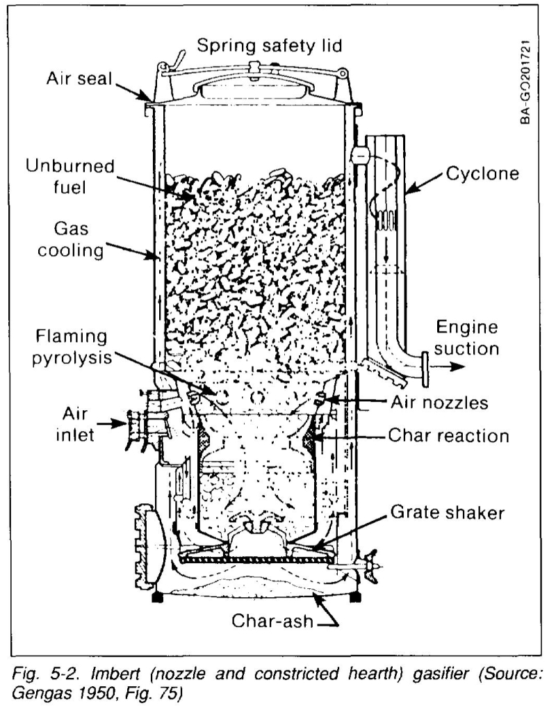
5.7.2 Description of the Downdraft (Imbert) Gasifier
Referring to Figs. 5-1 [re-number these] and 5-2, the upper cylindrical part of the inner chamber is simply a magazine for the wood chips or other biomass fuel. During operation, this chamber is filled every few hours as required. The spring-loaded cover is opened to charge the gasifier, and then it is closed during gasifier operation. The spring permits the cover to pop open to relieve pressure in the case of a gas explosion, thus functioning as a safety valve. About one-third of the way up from the bottom, there is a set of radially directed air nozzles that permit air to be drawn into the chips as they move down to be gasified. Typically. there are an odd number of nozzles so that the hot gases from one nozzle do not impinge on the opposite nozzle. The nozzles are attached to a distribution manifold that in turn is attached to the outer surface of the inner can. This manifold is connected through the outer can to a large air-entry port. One air nozzle is in line with this port, allowing the operator to ignite the charcoal bed through this nozzle. During operation, the incoming air burns and pyrolyzes some of the wood, most of the tars and oils, and some of the charcoal that fills the gasifier below the nozzles. Most uf the mass of biomass is converted to gas within this flaming combustion zone since biomass contains more than 80% volatile matter (Reed issaa). The gasifier is in many ways self-adjusting. If there is insufficient charcoal at the air nozzles, more wood is burned and pyrolyzed to make more charcoal. If too much char forms during high-load conditions, then the char level rises above the nozzles so that incoming air burns the char to reduce the char level. Thus, the reaction zone is maintained at the nozzles. Below the air nozzle zone lies the gas-reduction zone. usually consisting of a classical Imbert hearth (Fig. 5-2) or in later years, of the "V" hearth (Fig. 5-6).
Most recently, the flat-plate hearth constriction (Fig. 5-7) has been introduced. The latter two hearth designs accumulate a layer of retained ash to form a high-quality. self-repairing insulation. Improved insulation in the hearth results in lower tar production and a higher efficiency over a wider range of operating conditions. After the combustion/pyrolysis of wood and hot char at the nozzle level (see below), the resulting hot combustion gases (CO2 and H2O) pass into this hot char where they are partially reduced to the fuel gases CO and H2 according to Eqs. (4-7) and (4-8). This procedure results in a marked cooling of the gas, as sensible-gas heat is converted into chemical energy. This removes most of the charcoal and improves the quality of the gas. Eventually, the charcoal is "dissolved" by these gases and disintegrates to smaller chunks and a fine powder that either is swept out with the gases to the cyclone separator or falls through the grate.
Tars that have escaped combustion at the nozzle may crack further in the hot char although tar cracking is now thought to occur only above about 850°C (Kaupp 1984h; Diebold 1985). The spaces between the nozzles (shown in Fig. 5-8) allow some unpyrolyzed biomass to pass through. The hearth constriction then causes all gases to pass through the hot zone at the constriction, thus giving maximum mixing and minimum heat loss. The highest temperatures are reached in this section so the hearth constriction should be replaceable. If tarry gas is produced from this type of gasifier, common practice is to reduce the hearth constriction area until a low-tar gas is produced. However, one should remember that hearth dimensions also play a role in the gas production rate (see below). The fine char-ash dust can eventually clog the charcoal bed and will reduce the gas flow unless the dust is removed. The charcoal is supported by a movable grate that can be shaken at intervals. Ash builds up below the grate and can be removed during cleaning operations. Usually, wood contains less than 1% ash. However, as the charcoal is consumed, it eventually collapses to form a powdered char-ash that may represent 2% to 10% of the total biomass, in turn containing 10% to 50% ash. Ash contents depend on the char content of the wood and the degree of agitation. The greater the degree of char reduction, the smaller the resulting particles and the higher the ash, as shown in Fig. 3-3. The downdraft gasifier startup and response time is intermediate between the fast crossdraft gasifier and the slow updraft gasifier. The Imbert gasifier requires a low-moisture and uniformly blocky fuel in order to allow easy gravity feeding through the constricted hearth. Twigs, sticks, and bark shreds must be completely removed. The reduction in area at the hearth and the protruding nozzles present hazards at which the passage of fuel can be restricted, thus causing bridging and channeling followed by high tar output, as unpyrolyzed biomass falls into the reaction zone. The vehicle units of World War II had ample vibration to jar the carefully sized blocks through. In fact, an entire industry emerged for preparing car wood at that time.
An important factor used in choosing dimensions of any gasifier is the "superficial velocity, Vs," of the gas calculated where it passes through the narrowest part of the gasification zone. Although the units of Vs are length/time (e.g., m/s), one should think of the superficial velocity as gas production expressed in terms of gas volume/cross-sectional area-time (m3/m2-s), a specific gas production rate. It is called a superficial velocity since actual velocities will be three to six times higher due to the presence of the charcoal and the high temperatures existing at the throat. A closely related term is the maximum hearth load Bh, expressed in gas volume/hearth area-h, expressed in practical units. This term enables one to compare the performance of a wide variety of gasifiers on a common basis. The maximum specific hearth loads for a number of gasifiers are shown in Table 5-1
The table was calculated from data available on gasifiers that have been thoroughly tested and lists the maximum superficial velocity and heating load reported. Note that in European literature, hearth load is reported in gas volume units; in the United States, it is reported in energy units. In Generator Gas (Gengas 1950) a maximum hearth load (Bhmax) value for an Imbert-style gasifier is about 0.9 Nm3/h-cm2. ln other words, 0.9 m3 of gas is produced for each square centimeter of cross-sectional area at the constriction. This corresponds to a superficial gas velocity VS of 2.5 m/s (8.2 ft/s) calculated at NTP* from the throat diameter and ignoring the presence of fuel. This corresponds to a specific gas production rate of 9000 m3 of gas per square meter of cross-sectional area per hour (29,500 scf/ft2-h), If the gas has a (typical) energy content of 6.1 MJ/Nm3 (150 Btu/scf), this results in a specific energy rate of 54.8 GJ/m2-h (4.4 MBtu/ft2-h). The diameter of the pyrolysis zone at the air nozzles is typically about twice that at the throat, and Table 5-1 shows the hearth load on this basis also. This puts the hearth load for the Imbert type gasifier on a comparable basis to the stratified downdraft gasifier. Knowledge of maximum hearth lead permits one to calculate the size of hearth needed for various engine or burner sizes. Dimensions for a variety of Imbert-type gasifiers are shown in Tables 5-2 and 5-3.
The maximum hearth load is limited by many factors, such as the mechanical integrity of the char bed structure within the gasifier, degree of agitation, and the time available for conversion. High velocities can disturb the char and fuel bed, causing instability. If char fragments become dislodged and airborne, they may plug the bed or form channels. Therefore, a little agitation can effectively increase the maximum specific hearth load. The heating value of producer gas varies with flow rate, as shown in Fig. 7-20. Notice that the maximum efficiency for rice hulls occurs at twice the flow rate that produces the maximum heating value from rice hulls. This occurs because the combination of lower temperatures and low fow rate favors methane and tar production. Although the change in efficiency is small, the benefit of reducing tar production is substantial. Closely related to hearth area (Am) is the cross-sectional area of the air nozzles (tuyeres) (Am).
*NTP refers to the European practice of correcting gas volume measurements to a "normal temperature and pressure" of 0°C and 1 atmosphere. In the United States it is conventional to correct measured volumes to STP, "standard temperature and pressure." 77°F (or 25°C) and 1 atmosphere.
Early workers observed an optimum relationship between the hearth and nozzle areas. For instance, maximum power was obtained from 130-mm hearths that had five 12-mm nozzles. Any variation of either the nozzle or hearth ring from these dimensions caused a power reduction. Table 5-2 shows successful nozzle sizes for wood-fueled Imbert gas producers and the wider variation for nozzles used in successful Imbert and SGB gasifiers. (SGB units were used for 2-cycle pulsating flow engines.) A larger hearth diameter requires either a higher nozzle velocity or some other means to penetrate the deeper fuel bed. This leads to a higher pressure drop for larger hearths, placing an upper size limit on nozzle-fed downdraft gasifiers when gas flow is provided by engine vacuum. If the cross-sectional area of the nozzles is too small, there will be an excessive pressure drop in forming the air jets; if the cross-sectional area is too large, the air jets will have too low a velocity and the air will not penetrate the bed. The velocity of the air blast is shown in Table 5-2.
5.7.4 Turndown Ratio
Another important concept in sizing gasifiers is the "turndown ratio," the ratio of the highest practical gas generation rate to the lowest practical rate. The turndown ratio of World War II gasifiers varied between 3 for Imbert-style gasifiers with uninsulated V-hearth gasifiers and 18 for highly insulated V-hearth gasifiers. Vehicle operation requires turndown ratios of at least 8:1, making the need for insulation and proper sizing in high-turndown applications apparent. Although engineers often oversize equipment, this can be fatal in gasifier design. Heat losses tend to be independent of throughput and at low loads become disproportionately high. A low specific hearth load may also cause tar formation problems. A high turndown ratio is less important for electric generators and irrigation pumps that constantly operate at full capacity. In summary, the Imbert gasifier design has survived the test of time and mass production. It is relatively inexpensive, uses simple materials of construction, is easy to fabricate, and can be operated by motorists with a minimum of training. It supplies low-tar gas from highly volatile fuels with a high turndown ratio.
5.7.5 Disadvantages of the Imbert Design
Although the Imbert gasifier has been the prototype downdraft gasifier, it has a number of disadvantages. The hearth constriction seriously limits the range of biomass fuel shapes that can be successfully gasified without expensive cubing or pelletizing pretreatment. (The stratified-bed gasifiers currently under development at SERI and other facilities and discussed in Section 5.8 are free of constrictions and promise to broaden the range of fuels that can be gasified.) The Imbert gasifier requires a high-grade, usually hardwood, fuel, generally at least 2 cm along the smallest dimension with no more than 20% moisture. During World War II, stringent specifications were maintained on fuel production, which was carried out at a number of licensed factories. The Imbert design cannot be scaled-up to larger sizes because the air enters at the sides and is incapable of penetrating a large-diameter fuel bed unless the fuel size is increased proportionally. The tar level, while low (usually 5000 ppm), is still high enough to require extensive scrubbing and disposal procedures, Groenevold has studied the recycle of gases at the nozzle and developed improved understanding of the tar combustion and improved mixing methods shown in Fig. 5-9 to permit scaleup (Groeneveld 1980a,b).
Unfortunately, there is no overall theory of operation for Imbert gasifiers that would permit sizing the gasifier for fuels other than hardwood blocks. The geometry and flow of fuel and air are quite complex, making any attempts to model the gasifier very difficult tasks indeed. (More information is provided in later discussions.) Some efforts to scale the Imbert gasifier to larger sizes have realized a disastrous increase in tar production (Goss 1979; Graham 1983). However, researchers have met with more success when the fuel size has been increased with the gasifier size. Billets that were 8 cm in diameter and 15 cm long have operated well in large Imbert-style gasifiers used for heating applications (Makray 1984).