
FEMA Gasifier

The Stratified Downdraft Gasifier
1. What is a wood gas generator and how does it work?
This report is one in a series of emergency technology assessments sponsored by the Federal Emergency Management Agency (FEMA). The purpose of this report is to develop detailed, illustrated instructions for the fabrication, installation, and operation of a biomass gasifier unit (i.e., a "producer gas" generator, also called a 'wood gas' generator) that is capable of providing emergency fuel for vehicles, such as tractors and trucks, in the event that normal petroleum sources were severely disrupted for an extended period of time. These instructions have been prepared as a manual for use by any mechanic who is reasonably proficient in metal fabrication or engine repair.
1.1 Introduction
Fuel gas, produced by the reduction of coal and peat, was used for heating, as early as 1840 in Europe, and by 1884 it had been adapted to fuel engines in England. Before 1940, gas generator units were a familiar, but not extensively utilized, technology. However, petroleum shortages during World War II led to widespread gas generator applications in the transportation industries of Western Europe. (Charcoal-burning taxis, a related application, were still common in Korea as late as 1970.) The United States, never faced with such prolonged or severe oil shortages, has lagged far behind Europe and the Orient in familiarity with and application of this technology; however, a catastrophe could so severely disrupt the supply of petroleum in this country that this technology might be critical in meeting the energy needs of some essential economic activities, such as the production and distribution of food.
This report attempts to preserve the knowledge about wood gasification as put into practical use during World War II. Detailed, step-by-step procedures are presented in this report for constructing a simplified version of the World War II, Imbert wood gas generator. This simple, stratified, downdraft gasifier unit can be constructed from materials that would be widely available in the United States in a prolonged petroleum crisis. For example, the body of the unit consists of a galvanized metal garbage can atop a small metal drum; common plumbing fittings throughout; and a large, stainless steel mixing bowl for the grate. A prototype gasifier unit was fabricated from these instructions. This unit was then mounted onto the front of a gasoline-engine farm tractor and successfully field tested, using wood chips as the only fuel; see Fig. 1-1 (all figures and tables are presented at the end of their respective sections). Photographic documentation of the actual assembly of the unit, as well as its operational field test, is included in this report.
The use of wood gas generators need not be limited to transportation applications. Stationary engines can also be fueled by wood gasifiers to run electric generators, pumps, and industrial equipment. In fact, the use of wood gas as a fuel is not even restricted to gasoline engines; if a small amount of diesel fuel is used for ignition, a properly adjusted diesel engine can be operated primarily on wood gas introduced through the intake manifold. However, this report is concerned with the operation of four-cylinder gasoline engines rated from 10 to 150 horsepower. If more information is needed about operating gasifiers on other fuels (such as coal, charcoal, peat, sawdust or seaweed), a list of relevant literature is contained in the Bibliography at the end of this report.
The goal of this report is to furnish information for building a homemade wood gas generator made out of ordinary, available hardware, in order to get tractors, trucks, and other vehicles operating without delay, if a severe liquid fuel emergency should arise. Section 1 describes gasification principles and wood gas generators, in general, and gives some historical background about their operation and effectiveness. Section 2 contains detailed step-by-step instructions for constructing your own wood gas generator unit; illustrations and photographs are included to prevent confusion. Section 3 contains information on operating, maintaining, and trouble-shooting your wood gas generator; also included are some very important guidelines on safety when using your gasifier system.
The wood gasifier design presented in this report has as its origin the proven technology used in World War II during actual shortages of gasoline and diesel fuel. It should be acknowledged that there are alternate technologies (such as methane production or use of alcohol fuels) for keeping internal combustion engines in operation during a prolonged petroleum crisis; the wood gasifier unit described in this report represents only one solution to the problem.
All internal combustion engines actually run on vapor, not liquid. The liquid fuels used in gasoline engines are vaporized before they enter the combustion chamber above the pistons. In diesel engines, the fuel is sprayed into the combustion chamber as fine droplets which burn as they vaporize. The purpose of a gasifier, then, is to transform solid fuels into gaseous ones and to keep the gas free of harmful constituents. A gas generator unit is, simultaneously, an energy converter and a filter. In these twin tasks lie its advantages and its difficulties.
The first question many people ask about gasifiers is, 'Where does the combustible gas come from?' Light a wooden match; hold it in a horizontal position; and notice that while the wood becomes charcoal, it is not actually burning but is releasing a gas that begins to burn brightly a short distance away from the matchstick. Notice the gap between the matchstick and the luminous flame; this gap contains the wood gas which starts burning only when properly mixed with air (which contains oxygen). By weight, this gas (wood gas) from the charring wood contains approximately 20% hydrogen (H2), 20% carbon monoxide (CO), and small amounts of methane, all of which are combustible, plus 50 to 60% nitrogen (N2). The nitrogen is not combustible; however, it does occupy volume and dilutes the wood gas as it enters and burns in an engine. As the wood gas burns, the products of combustion are carbon dioxide (CO2) and water vapor (H2O).
The same chemical laws which govern combustion processes also apply to gasification. The solid, biomass fuels suitable for gasification cover a wide range, from wood and paper to peat, lignite, and coal, including coke derived from coal. All of these solid fuels are composed primarily of carbon with varying amounts of hydrogen, oxygen, and impurities, such as sulphur, ash, and moisture. Thus, the aim of gasification is the almost complete transformation of these constituents into gaseous form so that only the ashes and inert materials remain.
In a sense, gasification is a form of incomplete combustion; heat from the burning solid fuel creates gases which are unable to burn completely, due to insufficient amounts of oxygen from the available supply of air. In the matchstick example above, as the wood was burned and pyrolyzed into charcoal, wood gas was created, but the gas was also consumed by combustion (since there was an enormous supply of air in the room). In creating wood gas for fueling internal combustion engines, it is important that the gas not only be properly produced, but also preserved and not consumed until it is introduced into the engine where it may be appropriately burned.
Gasification is a physicochemical process in which chemical transformations occur along with the conversion of energy. The chemical reactions and thermochemical conversions which occur inside a wood gas generator are too long and too complicated to be covered here. Such knowledge is not necessary for constructing and operating a wood gasifier. Books with such information are listed in the Reference Section (see, for example, Reed 1979, Vol. II; or Reed and Das 1988).
The use of wood to provide heat is as old as mankind; but by burning the wood we only utilize about one-third of its energy. Two-thirds is lost into the environment with the smoke. Gasification is a method of collecting the smoke and its combustible components. Making a combustible gas from coal and wood began around 1790 in Europe. Such manufactured gas was used for street lights and was piped into houses for heating, lighting, and cooking. Factories used it for steam boilers, and farmers operated their machinery on wood gas and coal gas. After the discovery of large petroleum reserves in Pennsylvania in 1859, the entire world changed to oil - a cheaper and more convenient fuel. Thousands of gas works all over the world were eventually dismantled.
Wood gas generators are not technological marvels that can totally eliminate our current dependence on oil, reduce the impacts of an energy crunch, or produce long-term economic relief from high fossil fuel prices, but they are a proven emergency solution when such fuels become unobtainable in case of war, civil upheaval, or natural disaster. In fact, many people can recall a widespread use of wood gas generators during World War II, when petroleum products were not available for the civilian populations in many countries. Naturally, the people most affected by oil and petroleum scarcity made the greatest advancements in wood gas generator technology.
In occupied Denmark during World War II, 95% of all mobile farm machinery, tractors, trucks, stationary engines, fishing and ferry boats were powered by wood gas generators. Even in neutral Sweden, 40% of all motor traffic operated on gas derived from wood or charcoal (Reed and Jantzen 1979). All over Europe, Asia, and Australia, millions of gas generators were in operation between 1940 and 1946. Because of the wood gasifier's somewhat low efficiency, the inconvenience of operation, and the potential health risks from toxic fumes, most of such units were abandoned when oil again became available in 1945. Except for the technology of producing alternate fuels, such as methane or alcohol, the only solution for operating existing internal combustion engines, when oil and petroleum products are not available, has been these simple, inexpensive gasifier units.
Until the early 1980's, wood gasifiers all over the world (including the World War II designs) operated on the principle that both the fuel hopper and the combustion unit be airtight; the hopper was sealed with a top or lid that bad to be opened every time wood was added. Smoke and gas vented into the atmosphere while new wood was being loaded; the operator bad to be careful not to breathe the unpleasant smoke and toxic fumes.
Over the last few years, a new gasifier design bas been developed through cooperative efforts among researchers at the Solar Energy Research Institute in Colorado, the University of California in Davis, the Open University in London, the Buck Rogers Company in Kansas, and the Biomass Energy Foundation, Inc., in Florida (Reed and Das 1988). This simplified design employs a balanced, negative-pressure concept in which the old type of sealed fuel hopper is no longer necessary. A closure is only used to preserve the fuel when the engine is stopped. This new technology has several popular names, including 'stratified, downdraft gasification' and 'open top gasification.' Two years of laboratory and field testing have indicated that such simple, inexpensive gasifiers can be built from existing hardware and will perform very well as emergency units.
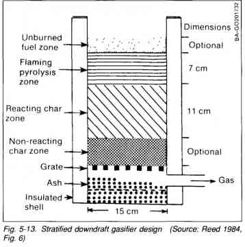
A schematic diagram of the stratified, downdraft gasifier is shown in Fig. 1-3. During operation of this gasifier, air passes uniformly downward through four zones, hence the name 'stratified:'
The uppermost zone contains unreacted fuel through which air and oxygen enter. This region serves the same function as the fuel hopper in the Imbert design.
In the second zone, the wood fuel reacts with oxygen during pyrolysis. Most of the volatile components of the fuel are burned in this zone and provide heat for continued pyrolysis reactions. At the bottom of this zone, all of the available oxygen from the air was completely reacted. The open top design ensures uniform access of air to the pyrolysis region.
The third zone is made up of charcoal from the second zone. Hot combustion gases from the pyrolysis region react with the charcoal to convert the carbon dioxide and water vapor into carbon monoxide and hydrogen.
The inert char and ash, which constitute the fourth zone, are normally too cool to cause further reactions; however, since the fourth zone is available to absorb heat or oxygen as conditions change, it serves both as a buffer and as a charcoal storage region. Below this zone is the grate. The presence of char and ash serves to protect the grate from excessive temperatures.
The stratified, downdraft design has a number of advantages over the World War II, Imbert gasifier. The open top permits fuel to be fed more easily and allows easy access. The cylindrical shape is easy to fabricate and permits continuous flow of fuel. No special fuel shape or pretreatment is necessary; any blocky fuel can be used.
The foremost question about the operation of the stratified, downdraft gasifier concerns char and ash removal. As the charcoal reacts with the combustion gases, it eventually reaches a very low density and breaks up into a dust containing all of the ash as well as a percentage of the original carbon. This dust may be partially carried away by the gas; however, it might eventually begin to plug the gasifier, and so it must be removed by shaking or agitation. Both the Imbert gasifiers and the stratified concept have a provision for shaking the grate; when they are used to power vehicles, they are automatically shaken by the vehicle's motion.
An important issue in the design of the stratified, downdraft gasifier is the prevention of fuel bridging and channeling. High-grade biomass fuels such as wood blocks or chips will flow down through the gasifier under the influence of gravity, and downdraft air flow. However, other fuels (such as shredded wood, sawdust, and bark) can form a bridge that will prevent continuous flow and cause very high temperatures. Obviously, it is desirable to use these widely available biomass residues. Bridging can be prevented by stirring, shaking, or by agitating the grate or by having it agitated by the vehicle's movement. For prolonged idling, a hand-operated shaker has been included in the design.
A prototype design of the stratified, downdraft gasifier design has been developed. The detailed but simple design is described and illustrated inSect. 2; however, it has not been widely tested at this time. The reader is urged to use his ingenuity and initiative in constructing his own wood gas generator. As long as the principle of airtightness in the combustion regions, in the connecting piping, and in the filter units is followed, the form, shape, and method of assembly is not important.
